- 您现在的位置:买卖IC网 > Sheet目录2000 > IDT821054PQF (IDT, Integrated Device Technology Inc)IC PCM CODEC QUAD MPI 64-PQFP
34
IDT821054 QUAD PROGRAMMABLE PCM CODEC WITH MPI INTERFACE
INDUSTRIAL TEMPERATURE RANGE
transmit PCM data. For compressed code (A/-Law), this register is not used (when being read, it will output a data byte of 00H).
The high byte of transmit PCM data will be read out by applying a read command to this register, and at the same time, it will be
transmitted to the PCM highway without any interference.
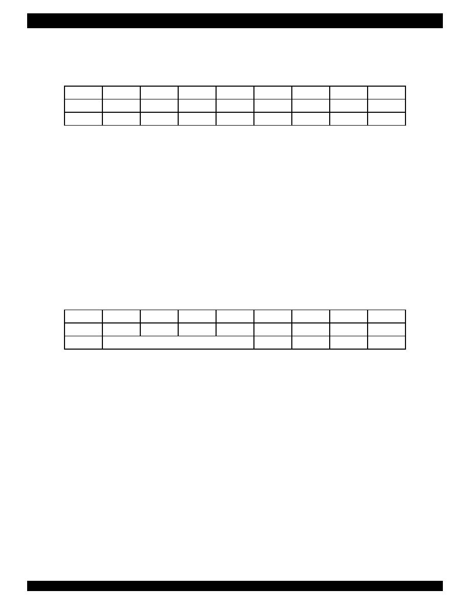
LREG9: A/D Gain, D/A Gain, Channel Power Down and PCM Receive Path Cutoff, Read/Write (08H/88H)
The Channel Power Down bit (PD) selects the operation mode for the corresponding channel:
PD = 0:
The corresponding channel is in normal operation state;
PD = 1:
The corresponding channel is powered down (default).
The PCMCT bit determines the operation of PCM Receive Path of the corresponding channel:
PCMCT = 0:
The PCM Receive Path of the corresponding channel is in normal operation state (default);
PCMCT = 1:
The PCM Receive Path of the corresponding channel is cut off.
The A/D Gain bit (GAD) sets the gain of analog A/D for the corresponding channel:
GAD = 0:
0 dB (default);
GAD = 1:
+6 dB.
The D/A Gain bit (GDA) sets the gain of analog D/A for the corresponding channel:
GDA = 0:
0 dB (default);
GDA = 1:
-6 dB.
Attention: To ensure proper operation, the lower 4 bits of the I/O data byte following the write command (88H) must be '0000'.
LREG10: Tone Generator Enable, Read/Write (09H/89H)
TEN1 = 0:
Tone generator 1 is disabled (default);
TEN1 = 1:
Tone generator 1 is enabled.
TEN0 = 0:
Tone generator 0 is disabled (default);
TEN0 = 1:
Tone generator 0 is enabled.
Attention: To ensure proper operation, the b3 and b2 of the I/O data byte following the write command (89H) must be ‘11’.
b7
b6
b5
b4
b3
b2
b1
b0
Command
R/W
0
0010
00
I/O data
PD
PCMCT
GAD
GDA
0
b7
b6
b5
b4
b3
b2
b1
b0
Command
R/W
0
0010
01
I/O data
Reserved
1
TEN1
TEN0
发布紧急采购,3分钟左右您将得到回复。
相关PDF资料
IDT82V3001APVG8
IC PLL WAN W/SGL REF INP 56-SSOP
IDT82V3010PVG
IC PLL WAN 51/E1/OC3 DUAL 56SSOP
IDT82V3011PVG
IC PLL WAN T1/E1/OC3 SGL 56-SSOP
IDT82V3012PVG8
IC PLL WAN T1/E1/OC3 DUAL 56SSOP
IDT82V3155PVG
IC PLL WAN T1/E1/OC3 DUAL 56SSOP
IDT82V3202NLG
IC PLL WAN EBU SGL 68-VFQFPN
IDT82V3255TFG
IC PLL WAN SMC STRATUM 3 64-TQFP
IDT82V3280APFG
IC PLL WAN SE STRATUM 2 100TQFP
相关代理商/技术参数
IDT821054PQFG
功能描述:IC PCM CODEC QUAD MPI 64-PQFP RoHS:是 类别:集成电路 (IC) >> 接口 - 编解码器 系列:- 标准包装:2,500 系列:- 类型:立体声音频 数据接口:串行 分辨率(位):18 b ADC / DAC 数量:2 / 2 三角积分调变:是 S/N 比,标准 ADC / DAC (db):81.5 / 88 动态范围,标准 ADC / DAC (db):82 / 87.5 电压 - 电源,模拟:2.6 V ~ 3.3 V 电压 - 电源,数字:1.7 V ~ 3.3 V 工作温度:-40°C ~ 85°C 安装类型:表面贴装 封装/外壳:48-WFQFN 裸露焊盘 供应商设备封装:48-TQFN-EP(7x7) 包装:带卷 (TR)
IDT821064
制造商:IDT 制造商全称:Integrated Device Technology 功能描述:QUAD PROGRAMMABLE PCM CODEC WITH GCI INTERFACE
IDT821064PQF
制造商:IDT 制造商全称:Integrated Device Technology 功能描述:QUAD PROGRAMMABLE PCM CODEC WITH GCI INTERFACE
IDT821068
制造商:IDT 制造商全称:Integrated Device Technology 功能描述:OCTAL PROGRAMMABLE PCM CODEC
IDT821068PX
制造商:IDT 制造商全称:Integrated Device Technology 功能描述:OCTAL PROGRAMMABLE PCM CODEC
IDT821621
制造商:IDT 制造商全称:Integrated Device Technology 功能描述:LONG HAUL SLIC
IDT821621J
制造商:IDT 制造商全称:Integrated Device Technology 功能描述:LONG HAUL SLIC
IDT8217LP35P
制造商:Integrated Device Technology Inc 功能描述: